Detalles de producto
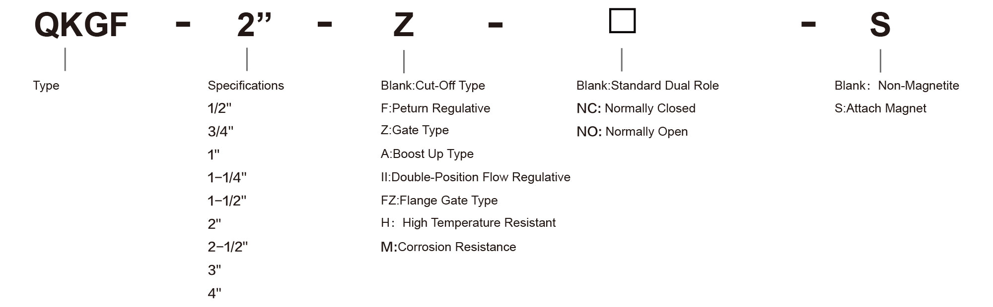
Código de pedido
![]()
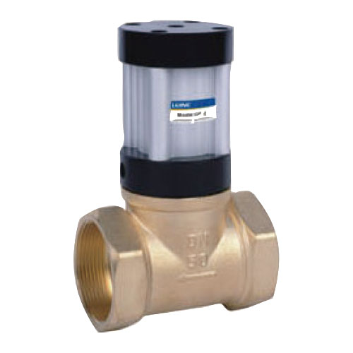
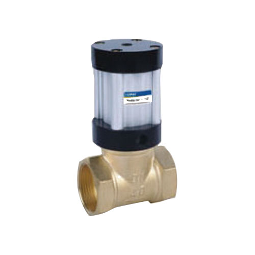
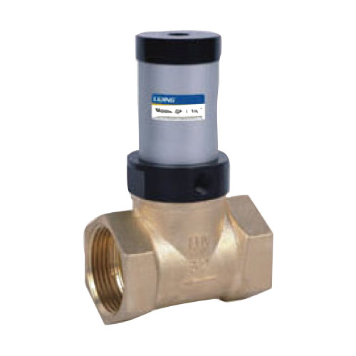
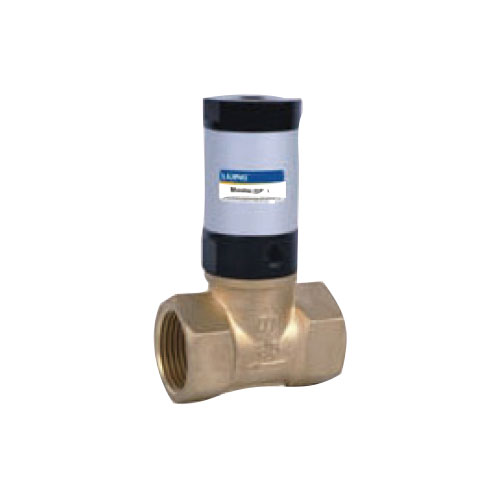
Sinopsis
La válvula de control neumático es un nuevo tipo de componente de control neumático diseñado y fabricado por nuestra empresa. La válvula se puede comprar de acuerdo con las necesidades de diferentes formas estructurales, como tipo de corte, tipo de compuerta, tipo de retorno ajustable y tipo ajustable de doble posición. Se ha utilizado ampliamente en alimentos, embalaje, petroquímica, metalúrgica, pulverización, vehículos y otros equipos mecánicos. Se pueden seleccionar y comprar varias formas estructurales, como el flujo medio ajustable, según las necesidades. El uso de una amplia gama de medios: adecuado para agua, aceite, gas, pulpa y otros medios líquidos.
![]()
Especificación
| Modelo | QKGF-1/2" | QKGF-3/4" | QKGF-1" | QKGF-1 1/4" | QKGF-1 1/2" | QKGF-2" | QKGF-2"F | QKGF-2"II | QKGF-2"A |
| Caudal de Abertura | 15 | 20 | 25 | 32 | 40 | 50 | 50 | 50 | 50 |
| Diámetro interior de tubo de conexión | Dentro = fuera= G1/8 | ||||||||
| Medio de Control | Aire Filtrado de 40 micrones | ||||||||
| Medio de Trabajo | Agua. | ||||||||
| Teperatura Operativa | -40~100℃ | ||||||||
| Presión de Control | 0.3~0.7MPa | 0.3~0.9MPa | |||||||
| PPresión de Trabajo | 0~0.7MPa | 0~0.8MPa | |||||||
| Comentario | Según la presión de trabajo, ajuste equivalente de la presión de control | ||||||||
![]()
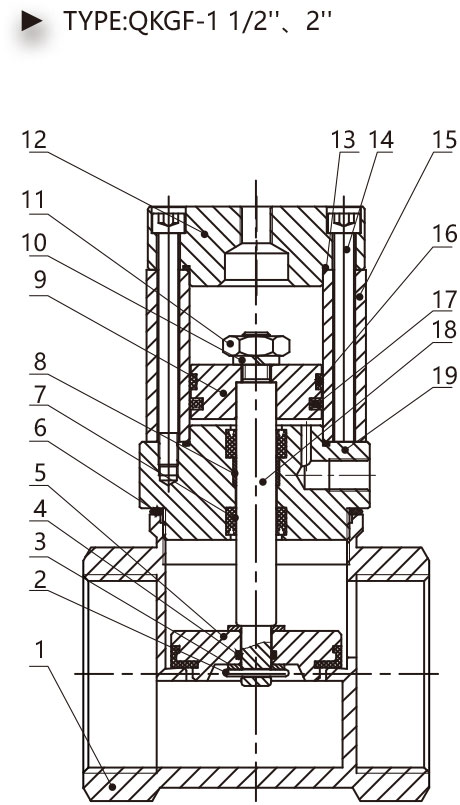
QKGF-2''
QKGF-1 1/2''
QKGF-1 1/4''
QKGF-1''
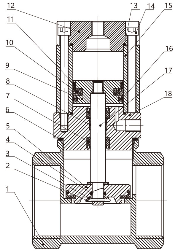
Construcción interior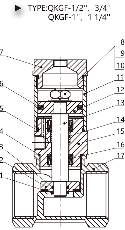
| Número de serie | Nombre |
| 1 | Alfiler |
| 2 | Elemento de Válvula |
| 3 | Elemento de Válvula de forma O |
| 4 | Cuerpo de Válvula de forma O |
| 5 | Tubo de forma O |
| 6 | Sellado de forma C |
| 7 | Contraportada |
| 8 | Tuerca |
| 9 | Arandera de bloqueo de muelle |
| 10 | Arandela estándar |
| 11 | Tubo de cilindro de aluminio |
| 12 | Émbolo |
| 13 | Vástago de émbolo |
| 14 | Bearing |
| 15 | Front Cover |
| 16 | Y-Ring Seal |
| 17 | Valve Body |
| Serial Numbe |
Name |
| 1 | Valve Body |
| 2 | Pin |
| 3 | Standard Gasket |
| 4 | Valve Element O-Ring |
| 5 | Valve Element |
| 6 | Valve Body O-Ring |
| 7 | Y-Ring Seal |
| 8 | Bearing |
| 9 | Piston |
| 10 | Sping Lock Washer |
| 11 | Nut |
| 12 | Behind Cover |
| 13 | Tube O-Ring |
| 14 | Socket Head Cap Screw |
| 15 | Aluminum Cylinder Tube |
| 16 | Wear-Ring |
| 17 | C-Ring Seal |
| 18 | Piston Rod |
| 19 | Front Cover |
![]()
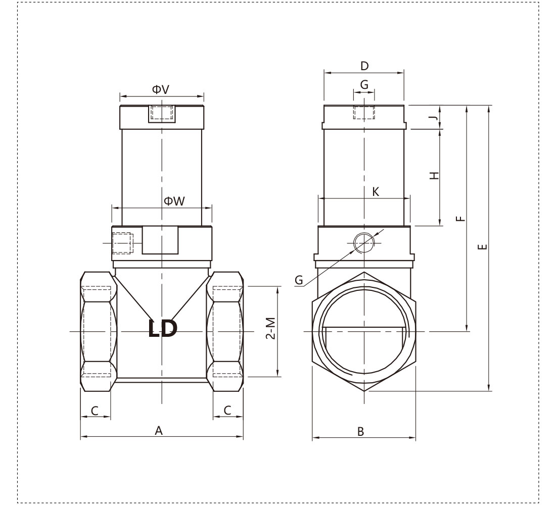
Dimensión total
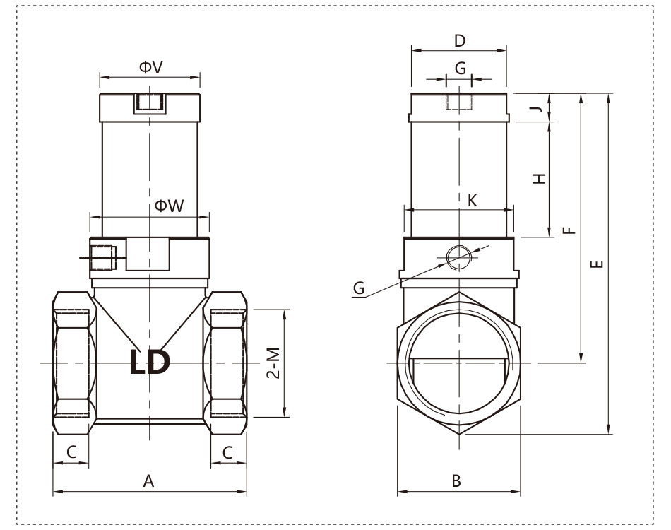
| Modelo | A | B | C | D | E | F | G | H | J | K | M | V | W |
| QKGF-1/2" | 47 | 26 | 12 | 24 | 97 | 82 | 1/8" | 34 | 11.5 | 27 | 1/2" | 26 | 29.7 |
| QKGF-3/4" | 54 | 32.5 | 14.5 | 30 | 103 | 84.5 | 1/8" | 34 | 11.5 | 30 | 3/4" | 31.7 | 31.7 |
| QKGF-1" | 62 | 39 | 14 | 37 | 118 | 96 | 1/8" | 39.5 | 11 | 37 | 1" | 39 | 39 |
| QKGF-1 1/4" | 76 | 48 | 14 | 37 | 134 | 108 | 1/8" | 45 | 11 | 45 | 1 1/4" | 39 | 48 |
| QKGF-1 1/2" | 83 | 54 | 18 | - | 162 | 131 | 1/8" | 51.6 | 19 | - | 1 1/2" | 65 | 65 |
| QKGF-2" | 104 | 66 | 22 | - | 178 | 140 | 1/8" | 51.6 | 19 | - | 2 | 65 | 65 |
![]()
QKGF-2''II
Inner Constuction
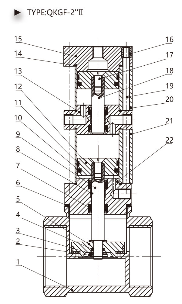
| Serial Numbe |
Name |
| 1 | Valve Body |
| 2 | Pin |
| 3 | Standard Gasket |
| 4 | Valve Element O-Ring |
| 5 | Valve Element |
| 6 | Valve Body O-Ring |
| 7 | Y-Ring Seal |
| 8 | Bearing |
| 9 | Front Piston Rod |
| 10 | ORing Seal |
| 11 | Wear-Ring |
| 12 | Piston |
| 13 | Middle Cover |
| 14 | Tube O-Ring |
| 15 | Behind Cover |
| 16 | Tie Rod Nut |
| 17 | Bolt |
| 18 | Behind Piston Rod |
| 19 | Tie Rod |
| 20 | Behind Cylinder Tube |
| 21 | Front Cylinder Tube |
| 22 | Front Cover |
![]()
Synopsis
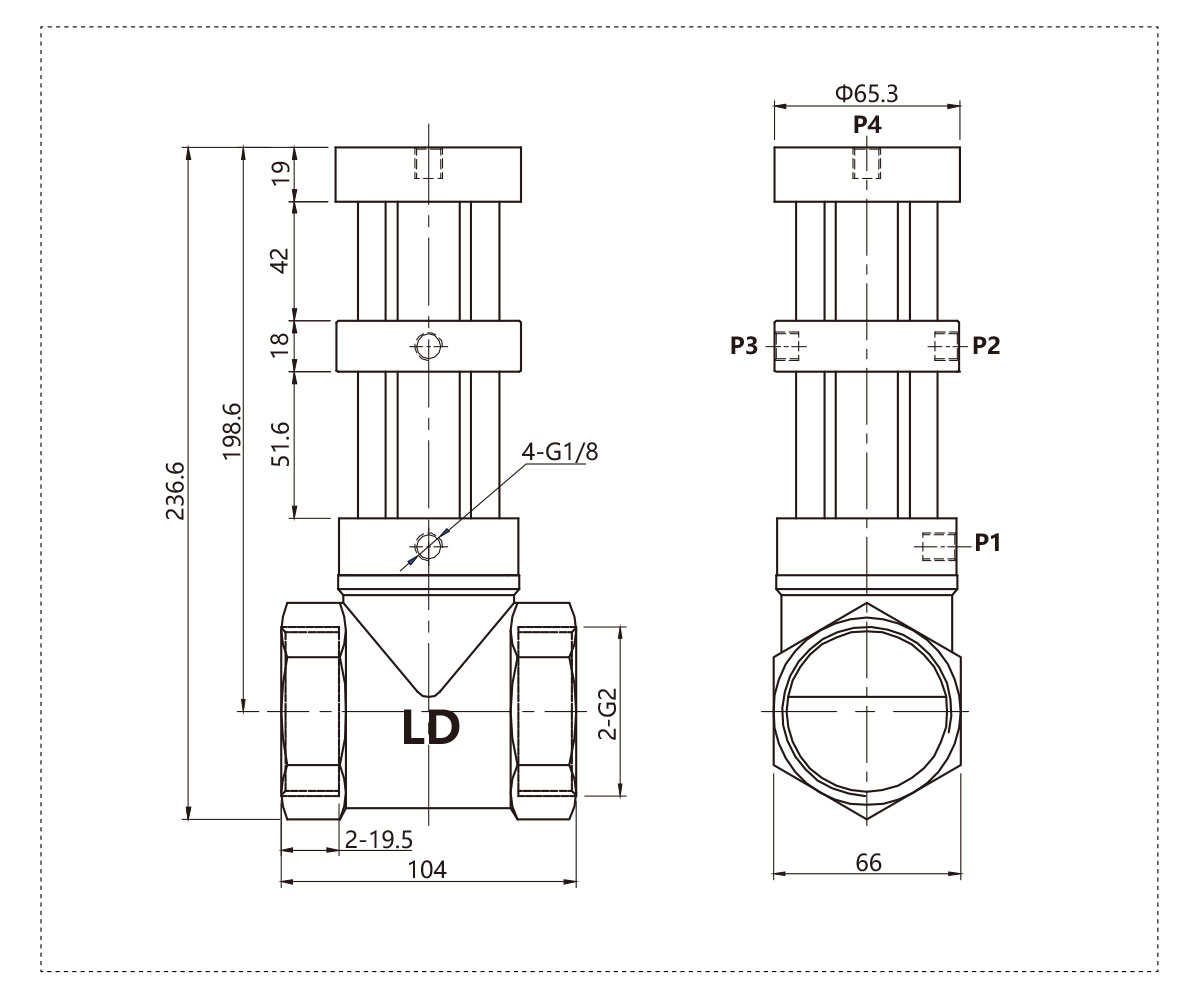
The valve is double position flow adjustable type,when P2 intake, the valve closes: when P1 and P3 intake, the valve opens completely; when P4 intake,the valve opens half.
Note: The intake pressure of P3 and P4 must be more than 0.1 MPa larger than that of P1 and P2 ports in the use process, so that these spools can play a balancing role.
![]()
Overall Dimension
![]()
QKGF-2''F
Inner Constuction
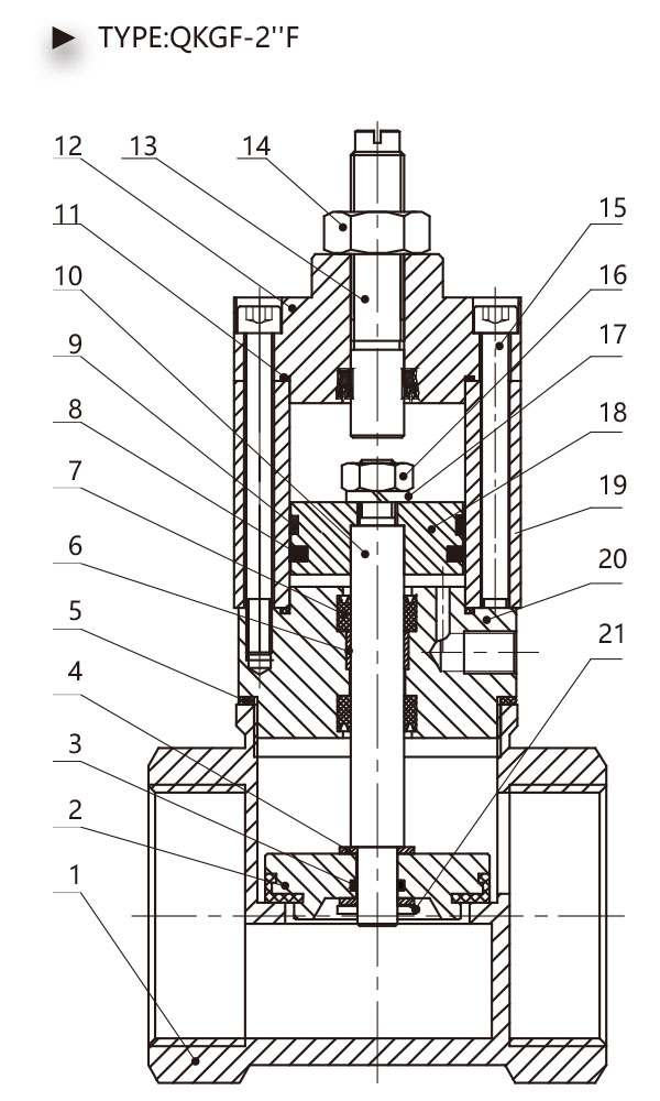
| Seria Numbe |
Name |
| 1 | Valve Body |
| 2 | Valve Element |
| 3 | Valve Element O-Ring |
| 4 | Standard Gasket |
| 5 | Valve Body O-Ring |
| 6 | Bearing |
| 7 | Y-Ring Seal |
| 8 | C-Ring Seal |
| 9 | Wear-Ring |
| 10 | Piston Rod |
| 11 | Tube O-Ring |
| 12 | Front Cover |
| 13 | Adjust Rod |
| 14 | Nut |
| 15 | Socket Head Cap Screw |
| 16 | Nut |
| 17 | Sping Lock Washer |
| 18 | Piston |
| 19 | Aluminum Cylinder Tube |
| 20 | Front Cover |
![]()
Synopsis
The valve is a return flow adjustable type. The opening height of the valve can be controlled by adjusting the adjusting screw on the back cover to achieve the purpose of regulating the flow.
Note: Nuts must be tightened after the flow regulation is completed to prevent the screw rotation from changing the flow rate.
![]()
Overall Dimension
![]()
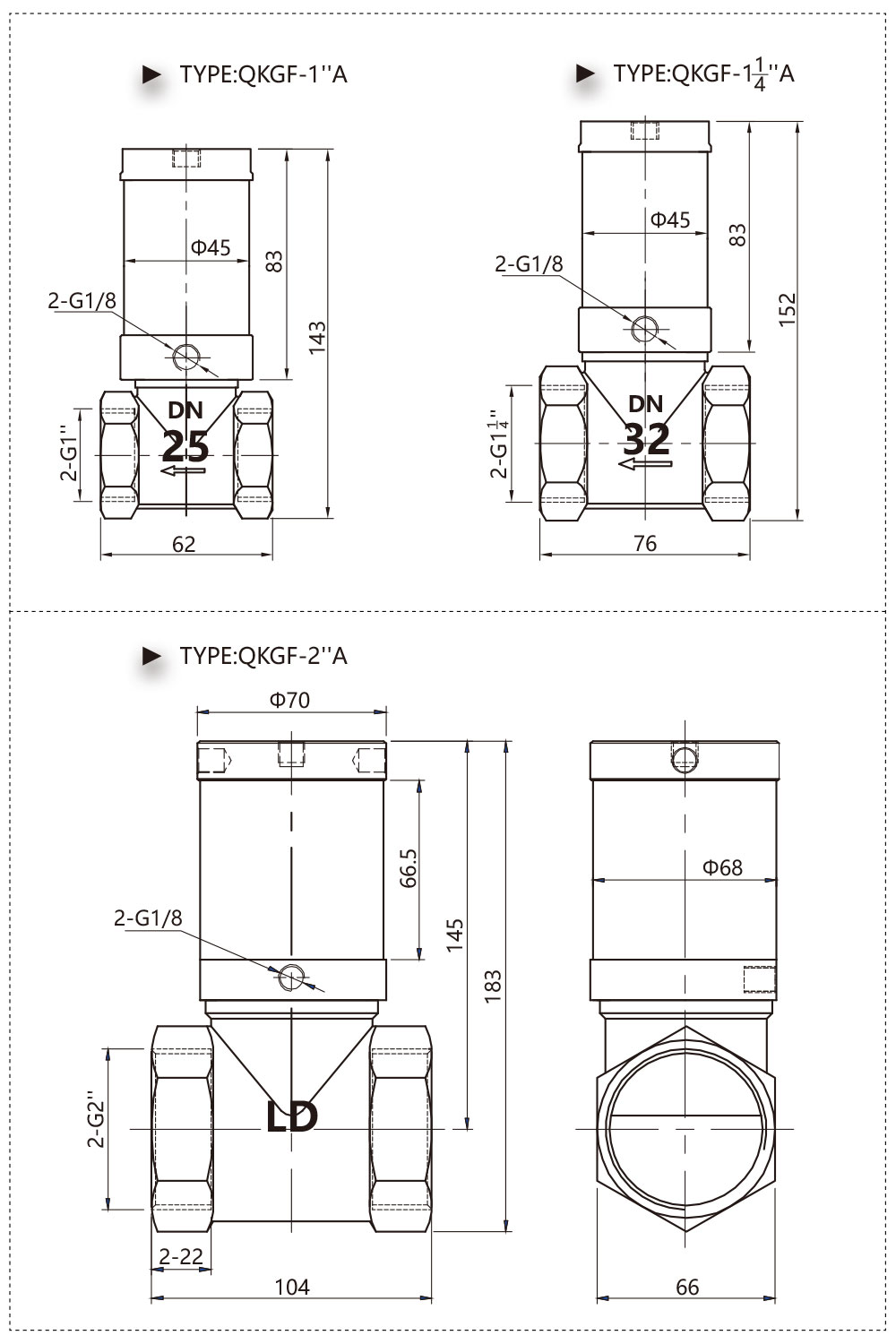
QKGF-1 1/4''A
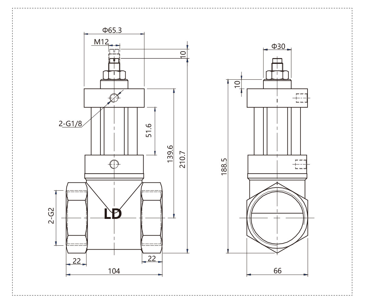
QKGF-2''A
Inner Constuction
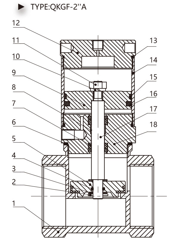
| Serial Numbe |
Name |
| 1 | Valve Body |
| 2 | Pin |
| 3 | Standard Gasket |
| 4 | Valve Element O-Ring |
| 5 | Valve Element |
| 6 | Valve Body O-Ring |
| 7 | Y-Ring Seal |
| 8 | Bearing |
| 9 | Piston |
| 10 | Sping Lock Washer |
| 11 | Nut |
| 12 | Behind Cover |
| 13 | Tube O-Ring |
| 14 | Aluminum Cylinder Tube |
| 15 | Wear-Ring |
| 16 | C-Ring Seal |
| 17 | Piston Rod |
| 18 | Front Cover |
![]()
Synopsis
La válvula es una estructura sobrealimentada, que logra el propósito de sobrealimentarse cambiando el área de fuerza del cilindro en la parte de control.
Adecuado para situaciones donde el fluido interno tiene requisitos de presión y sellado.
![]()
Dimensión global
![]()
QKGF-2''S
QKGF-1½''S
QKGF-1¼''S
QKGF-1''S
Construcción interior
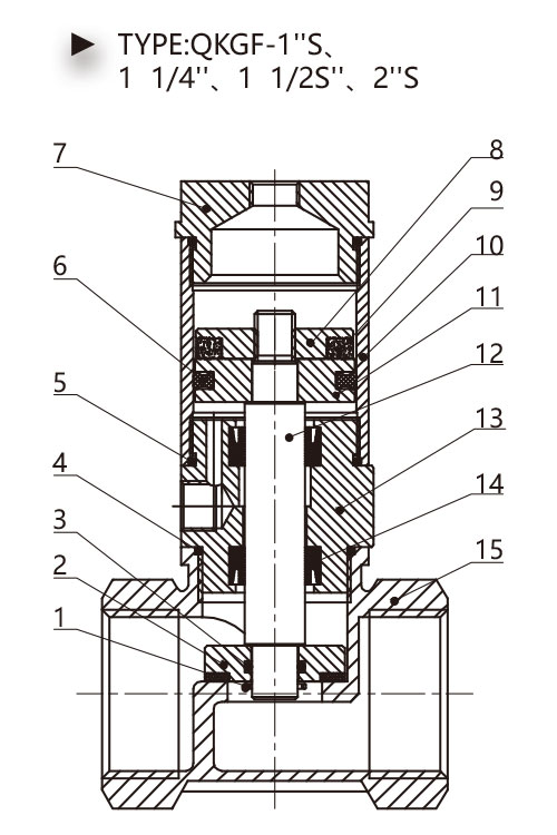
| Seria Numbe |
Nombre |
| 1 | Alfiler |
| 2 | Elemento valvular |
| 3 | Junta tórica del elemento de válvula |
| 4 4 | Junta tórica del cuerpo de la válvula |
| 5 5 | Junta tórica de tubo |
| 6 6 | Sello de anillo en C |
| 7 7 | Detrás de la cubierta |
| 8 | Estator magnético |
| 9 9 | Imán |
| 10 | Tubo de aluminio del cilindro |
| 11 | Pistón de imán |
| 12 | Vástago de émbolo |
| 13 | Cubierta de la barra |
| 14 | Junta tórica |
| 15 | Cuerpo de la válvula |
Numbe en serie |
Nombre |
| 1 | Cuerpo de la válvula |
| 2 | Alfiler |
| 3 | Junta estándar |
| 4 4 | Junta tórica del elemento de válvula |
| 5 5 | Elemento valvular |
| 6 6 | Junta tórica del cuerpo de la válvula |
| 7 7 | Junta tórica |
| 8 | Llevando |
| 9 9 | Pistón |
| 10 | Imán |
| 11 | Anillo de desgaste |
| 12 | Detrás de la cubierta |
| 13 | Junta tórica de tubo |
| 14 | Tornillo de cabeza hueca |
| 15 | Tubo de aluminio del cilindro |
| dieciséis | Sello de anillo en C |
| 17 | Vástago de émbolo |
| 18 años | Cubierta de la barra |
![]()
Dimensión global
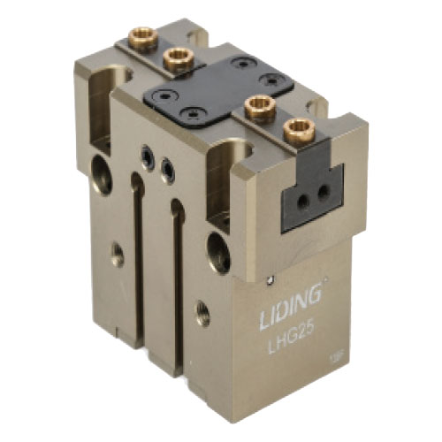
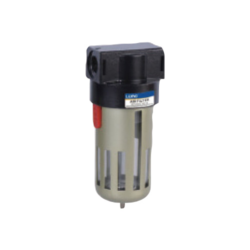
Productos Recomendados
Déjanos un mensaje
¿Qué estás buscando?
Derechos de autor © Ningbo Lida neumática completa Co., Ltd.